Thursday, May 9, 2013

Mutevoli


I finally decided to name my piece Mutevoli which means ever changing because I intentionally created the visual to constantly being drawing over itself as each consecutive person interacted with the piece. This represents how in life we as people are constantly growing and changing and our lives are constantly changing too.  I often fear to some extent and avoid to a large extent, change. And even in creating art I often do not push myself to explore far enough because I find one pattern or combination that I like so I stop so as to keep from ruining what I have achieved so far allowing fear of failure to keep me from possibly achieving something even better. So this piece for me was a piece that was built to change so that I could not control it. It was up to other people to continually recreate the piece. This also symbolized for me the degree to which other people's lives intertwine with your own and how other people can change your life even if do not intend for them to.

"To exist is to change, to change is to mature, to mature is to go on creating oneself endlessly." - Henri Bergson


Other people seemed to enjoy the piece at Vizagogo. Though it may not have had the same meaning for everyone as it did for me I enjoyed watching people happily interact with my piece. Children loved it and I was glad that it held up against their extreme interaction with it. One girl told me she found it very therapeutic while one woman asked me if I had patented it, and another woman even told me that she wanted one for her home.

Here are some videos of the piece in action: 
(Unfortunately, the embedding is not working today so I posted them on Youtube and have supplied the links here)

 http://www.youtube.com/watch?v=2MLvU9bpzxM

http://www.youtube.com/watch?v=mu9lyMZK9OQ&feature=youtu.be
 

Thursday, April 25, 2013

Final Project Update

It's been a while, but I've been busy working hard. Here is an update on my progress:

Things that I have done/working:
  • The screen is built. I used spandex and pvc pipe to construct a screen that stands 6 ft tall and 6'4" across. The interaction with the screen itself is very nice. The spandex is soft and inviting to touch
  • I have the kinect software running smoothly in Visual Studio. After writing some calibration code I am getting a very clean read on the screen (no noise). I had attempted to use Processing originally, but after finally winning the battle to get all of the kinect and opencv libraries that I needed running with Processing on my 64 bit Windows 7 machine, I was dismayed to discover that these libraries used a hacked Kinect driver rather than the official driver released by Microsoft. I am blaming this driver for the terrible lack of quality in the depth information that I was getting from the Kinect in Processing. I decided to go back to the official Windows SDK and learn Direct2D.
  • I have a visual application that generates rectangles which are rotated according to how far the screen is being displaced inward. The rectangles are sized according to the radius of the area of the screen that is displaced. This is not the original application that I had planned, but it is visually appealing and fun to interact with. It kind of grew out of my methods for debugging my program to detect areas of pressure on the screen. To detect these pressure points I process the depth image from top left corner to the right and then down. I simply check if the depth at a pixel is greater than zero and then check all of the currently existing "blocks" of pressure/depth which only store the start and max x and y coordinates. I see if this pixel is within a threshold distance of the x or y max then add this pixel to the block by updating the appropriate max value. This is a very fast and efficient way to detect multiple disjoint areas of pressure on the screen. 
Here are some images that my installation has created:


Things that Dont Work or Aren't Finished:
  • I am having trouble with a hotspot showing through from the projector. I think my screen is just too thin. You can see straight through the fabric. I thought that offsetting the projector would fix this, but my screen is too big to get the hotspot out of viewing range. I have also tried putting some diffusing materials like wax paper or dryer sheets in front of the projector light but these solutions do not work.
  • I originally proposed a fractal exploration application for the screen which I would still like to complete. I have mostly implemented an image sequence exploration application which parses through the frames of the image or video sequence to the depth of the displacement and then plays the video back to the first frame. I plan to make a fractal zoom video using Mandelbulb3D and then use the image sequence viewing technique allow users to interactively explore the fractal
Videos Coming Soon!

Tuesday, March 26, 2013

Final Project Idea


I finally figured out what I want to do for my final project!
It involves touch based interaction, movement, and projection

Here are two projects that are basic variations on what I want to do:

Firewall
http://www.amusement.net/2012/12/21/firewall-spandex-and-a-kinect-make-for-a-great-interactive-installation/


Khronos Projection
http://www.k2.t.u-tokyo.ac.jp/members/alvaro/Khronos/
(I absolutely love this one! I love how the aspect of time is also involved in this one!!!)


I was thinking of introducing a difference between these pieces and my piece by allowing the spandex to be able to be touched and deform accordingly, but I would also have the canvas moving itself. I could use some simple motors to create this motion but I am actually moving away from this thought now.

Actually now I am thinking of combining this with some of my thesis research ideas. I am very intrigued and involved with the creation of  systems to ease the interaction with a digital 3D world by using traditional clunky 2D interfaces and non-intuitive tools such as keyboard and mouse. I realize that this pushing into the fabric gives us access to a third dimension that I would love to leverage to the advantage of the creation of 3D animation and art. Therefore, I will create an interactive art piece (most likely based on some sort of physics simulation) that reacts/animates due to the user's input on this screen in 3 dimensions. Then later I can extend the piece to be an actual tool for interacting with 3D software such as Maya by allowing the creation of 3D curves and the placement of objects in 3D space.

What I will need:
  • A large piece of spandex
  • Kinect (or an IR sensor)
  • Projector
  • (Maybe: Arduino and motors)
(I will update this timeline as my ideas take a more solid form and the problem areas develop in the project. My main concern right now is figuring out the best way to get the fine grain control over sensing the position/placement of user's touch on the canvas in 3 dimensions)
Timeline:

  • Week 1:
    • Acquire Supplies
    • Generate basic installation setup (configure a stand for the fabric, figure out how to set up projector and Kinect)
    • Get the projector to communicate with my laptop
    •  Download Kinect software and get it running on laptop
  • Week 2:
    • Learn the basics of interacting with the Kinect
    • Get the Kinect to recognize motions of the fabric in 3 dimensions (If the interaction is not fine grain enough we will have to move to the IR sensor)
    • Finalize idea for projected images and interaction
  • Week 3:
    • Get basic Simulation(or projection interaction) working
  • Week 4:
    • Get everything that didn't go right the first time around working and work out bugs
  • Week 5:
    • Plan on finishing early because you won't really

Final Project Inspiration


In brainstorming for the final project, here are some concepts and pieces that I find interesting:

I really like the idea of giving objects or machines personalities. Terry Border does just this in a simple yet effective way with his sculptures.
http://wildammo.com/2012/03/22/living-objects-if-household-items-food-came-alive/#14
household-items-come-alive-wildammo (4)


As I mentioned before I really love mechanical sculptures. The work of David C. Roy is probably my favorite of these kinetic sculptures. His are wound springs, but I could do something similar with Arduino motors. I have never done wood working though.
http://www.woodthatworks.com/


I love both of these pieces. They are so simple yet use motion to become memorizing.
I could definitely see myself creating a similar piece using pendulum motion to create an intriguing computer powered kinetic sculpture


I also love the work of Gideon Obarzaneks. I have been playing with the idea of using projection in my final project and I think even though he works with dancers and I would not be in this case, great inspiration can be drawn from the unique ways he uses projections with motion to evoke emotions


Project 3 - Motors


Sure people paint walls, but walls are still mostly a functional housing unit, but they could be so much more. By giving walls movement, they could become points of intrigue and interactive art pieces all on their own. These are the ideas that served as inspiration for my theoretical motors project


This is the hyposurface wall. A quote from their website states, "The Hyposurface allows participants to connect and interact with a massive, powerful force - its like controlling a waterfall." I love this idea of a sort of butterfly effect. One small touch has dramatic effects across something much larger.


This installation is called The Reef. I like this one for completely opposite reasons.  The movement here is gentle and quiet. It exudes a peacefulness that is a bit unexpected from a large wall, but I love the actual elicitation of emotion that I feel from this piece.


My proposed idea is a bit of a combination of both of these pieces. When I first thought of a moving wall I began to think of it as a living creature which led to me wanting it to breath. I then thought of the wall as the side of a giant, mystic creature like a dragon and thought of it as covered in scales. I found the following photograph extremely beautiful and think it would serve as a concept art for the look of the wall.


So the wall would be covered in these scales and each scale would have two motors and a pressure sensor attached to it. The entire wall would move in and out in a steady rhythm (with the middle moving more than the sides in a sort of parabolic surface shape - imagine the side of a dragon). In my mock up I have the servo motor controlling this motion since I can get a very steady rhythm with this motor. Then when the wall is touched the scale where the wall is touched and the surrounding scales ruffle out in a ripple effect. In my mock-up I have this motion controlled by the stepper motor.

Here is a diagram of my Arduino setup for this project:


And here is my code for this project:


#include <Stepper.h>
#include <Servo.h>
 
// change this to the number of steps on your motor
#define STEPS 48
Stepper myStepper(STEPS, 8, 9, 10, 11);
Servo myServo;  // create servo object

int pressPin = A7;
int press_val = 0;
int prev_press_val = 0;

int potpin = 0;  // analog pin used to connect the potentiometer
int pot_val = 0; // variable to read the value from the analog pin

void setup()
{
  // set the speed of the motor to 100 RPM
  myStepper.setSpeed(150);
  myServo.attach(2);  // servo control signal sent out pin 9
 
  Serial.begin(9600);
}

void breath()
{
  boolean interrupt = false;
  while(!interrupt)
  {
    for(int i=0; i<100; i++)
    {
      myServo.write(i);
      delay(15);
    }
    for(int i=0; i<400; i++)
    {
      press_val = analogRead(pressPin);
      Serial.println(press_val);
      if(press_val>50){interrupt = true;break;}
      delay(1);
    }
    //delay(1000);
    for(int i=100; i>0; i--)
    {
      myServo.write(i);
      delay(15);
    }
    for(int i=0; i<400; i++)
    {
      press_val = analogRead(pressPin);
      Serial.println(press_val);
      if(press_val>50){interrupt = true;break;}
      delay(1);
    }
    //delay(1000);
    //see if there was a change in the pressure value
    press_val = analogRead(pressPin);
    Serial.println(press_val);
    if(press_val>50){interrupt = true;}
   
  }
}
void loop()
{
   while(true){
    breath();
    myStepper.step(40);
    delay(100);
    myStepper.step(-40);
  }

 }

Tuesday, March 5, 2013

Project 2 Results

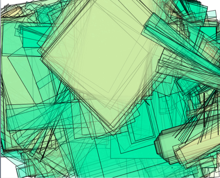
Here is a result video from my theoretical project described in the previous blog:

I left the inherent noise in the readings from the accelerometer to give the image more visual interest.
You can see the lines being drawn here change color as I squeeze the pressure sensor and the lines move around the screen as I tilt the accelerometer.

Some suggestions from class that would be nice to add to this are that in order to incorporate time into the generated piece I could have the color palette shift from cool to warm as the day progresses so that the older lines will push back into the page and the newer,warmer lines will come forward. Also playing with the thickness of the line being drawn would be more interesting. However, this was just a theoretical project. I would have to actually make a wearable device and try it over the course of an entire day to see if it generated something that I was happy with.

Here is a schematic of my Arduino board setup:


Here is my code for this project:

This is the Arduino file:


int R = 14;
int G = 16;
int B = 15;

int X = A8;
int Y = A9;
int Z = A10;

int x_val = 0;
int y_val = 0;
int z_val = 0;

int prev_x = 0;
int prev_y = 0;
//int base_z = 798;

int r_val = 0;
int g_val = 0;
int b_val = 0;
 int inc_val = 5;
 int r_inc = inc_val;
 int g_inc = 0;
 int b_inc = 0;

int pressPin = A12;
int press_val = 0;
int prev_press_val = 0;

int r = 0;
int g = 0;
int t = 0;

/* 5V input
int base_x = 518;
int base_y = 515;
int base_z = 798;
*/

//3.3 Volt
int base_x = 365;
int base_y = 335;
int base_z = 492;

int scale = 100;

String send_to_serial = "";

const int ledPin[10] =  {
  4,5,6,7,8,9,10,11,12,13};      // the number of the LED pins
int ledState = 0;

void setup()
{

  Serial.begin(9600);

  // initialize the digital pin as an output.
  pinMode(R, OUTPUT);
  pinMode(G, OUTPUT);
  pinMode(B, OUTPUT);

   // set the digital pin as output:
  for(int i = 0; i < 10 ;i++){
    pinMode(ledPin[i], OUTPUT);
  }
}

void loop()
{
  send_to_serial = "";
 
  //might not get anything from tilt in this case...
 
  //read the accelerometer and subtract off base/rest value
  x_val = analogRead(X) - base_x;
  y_val = analogRead(Y) - base_y;
  z_val = analogRead(Z) - base_z;
 
  //take the difference between the last time and this time
  int delta_x = x_val - prev_x;
  int delta_y = y_val - prev_y;
 
 //If the pressure sensor is squeezed change the color
 press_val = analogRead(pressPin);

 //calculate the current color
 if(press_val>prev_press_val)
 {
    //increment the color
    if((r_inc==inc_val && r_val>=255) || (r_inc==-inc_val && r_val<=0))
    {
       if(r_val>=255)
       {
         r_val=255;r_inc=0;
         if(b_val>=255){ b_inc=-inc_val;}
         else{g_inc=inc_val; b_inc = 0;}
       }
       if(r_val<=0){r_val=0;r_inc=0;b_inc=inc_val;}
    }
    if((g_inc==inc_val && g_val>=255) || (g_inc==-inc_val && g_val<=0))
    {
      if(g_val>=255)
      {
        g_val=255;g_inc=0;
        if(r_val>=255){r_inc=-inc_val;}
        else {b_inc = inc_val;r_inc=0;}
      }
      if(g_val<=0){g_val=0;g_inc=0;r_inc=inc_val;}
     }
      if((b_inc==inc_val && b_val>=255) || (b_inc==-inc_val && b_val==0))
      {
        if(b_val>=255)
        {
         b_val=255;b_inc=0;
         if(g_val>=255){g_inc=-inc_val;}
         else{ r_inc=inc_val;g_inc=0;}
        }
        if(b_val<=0){b_val=0;b_inc=0;g_inc=inc_val;}
       }
       
      r_val+=r_inc;
      g_val+=g_inc;
      b_val+=b_inc;
       
 }

 //Send the information to Processing using the Serial Port
 send_to_serial.concat(x_val);
 send_to_serial.concat(' ');
 send_to_serial.concat(y_val);
 send_to_serial.concat(' ');
 send_to_serial.concat(z_val);
 send_to_serial.concat(' ');
 send_to_serial.concat(r_val);
 send_to_serial.concat(' ');
 send_to_serial.concat(g_val);
 send_to_serial.concat(' ');
 send_to_serial.concat(b_val);

 int press_led = map(press_val,0,200,0,10);
 for(int i=0; i<10; i++)
 {
   if(i<=press_led){digitalWrite(ledPin[i],HIGH);}
   else{digitalWrite(ledPin[i],LOW);}
 }
// Serial.print(press_led); Serial.print(" "); Serial.println(press_val);

 //This is actually how Processing gets the values
 Serial.println(send_to_serial);
 delay(100); //small delay to let buffer settle and slow down draw

 //show what color is currently being drawn through the first LED
 digitalWrite(R,r_val);
 digitalWrite(G,g_val);
 digitalWrite(B,b_val);

 //reset the prev values for next loop
 prev_x = x_val;
 prev_y = y_val;
 prev_press_val = press_val;
}


This is the Processing file:


import processing.serial.*;

 Serial myPort;        // The serial port
 int xPos = 1;         // horizontal position on screen
 int yPos = 1;         // vertical position on screen

 int w = 400;
 int h = 300;

 float prev_x = random(width);
 float prev_y = random(height);

 void setup () {
 // set the window size:
 size(400, 300);      

 // List all the available serial ports
 println(Serial.list());
  myPort = new Serial(this, Serial.list()[0], 9600);
   // don't generate a serialEvent() unless you get a newline character:
   myPort.bufferUntil('\n');
   // set inital background:
   background(0);
 }

 void draw () {
 // everything happens in the serialEvent()
 }

 void serialEvent (Serial myPort) {
   // get the ASCII string:
   //We get a line that contains x y z r g b
   String inString = myPort.readStringUntil('\n');
 
   if (inString != null) {
       // trim off any whitespace:
       inString = trim(inString);
       String[] list = split(inString, ' ');
     
       int x,y,z,r,g,b;
     
       // convert to ints
       if(list.length==6)
       {
         x = int(list[0]);
         y = int(list[1]);
         z = int(list[2]);
         r = int(list[3]);
         g = int(list[4]);
         b = int(list[5]);
       }
       else
       {
         //info incorrect so skip this one
         return;
       }
     
       noFill();
       stroke(r,g,b); //we will set this color using the pressure
     
       x = int(map(x, -180,180,0,width));
       y = int(map(y, -180,180,0,height));
       line(prev_x, prev_y, x, y);
       //arc(random(width), random(height) , width, height, roll, pitch);
     
       prev_x = x;
       prev_y = y;

   }
 }


Thursday, February 28, 2013

Project 2

We were once again supposed to create a theoretical art piece and build a mock-up of it with our Arduinos.
We were supposed to use 2 sensor inputs and 2 LED outputs and Serial communication.

I wanted to use Processing this time around (Since Processing communicates with the Arduino via Serial I am counting this as my use of Serial communication.). For this project, I found myself very inspired by the following computer generated art pieces. I love the sense of chaos and yet rhythm that they have.


At the same time I thought about how I never seem to make enough time to explore my creative ideas. I am usually too wrapped up in the things that I have to do for school or work to spend much time on the grandiose ideas of my mind. So I have started daily challenging myself with this question (and I encourage you to do the same): "What have you created today?"

So I decided to make a system that would take the natural rhythm of  daily activity and express it in a generative art piece so that at the end of the day you could have automatically created a piece of art for the day. It uses an accelerometer to track your motion(maybe you would wear it on your foot or just your shirt) and a pressure sensor (maybe to detect touch or steps). My Processing program uses the accelerometer data as an (x,y) coordinate to determine where on the screen it should draw and the pressure sensor data changes the color


(Code and Video will be in next blog post)